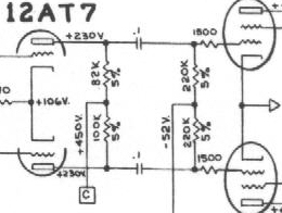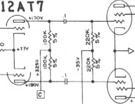
Plate load resistors on the phase inverter:
Fender went to an 82k plate load resistor
presumably to balance the halves of the signal coming off the phase inverter.
They also installed 1500 ohm resistors in series with the grids of the
power tubes to dampen oscillation if there is any. Here is what the AB763
looks like:

Here is what the AA763 looks like:

Here is what the AB763 plate load resistors
on the layout look like (the plate load resistors are the 100k and 82k's):

Then the AA763:

Notice the 82k resistor that got added.
Now the power tube sockets, and how the 1500 ohm grid stoppers got installed:
(AB763)

Then the AA763:

See how Fender just put them across the tube socket? These resistors are a good idea. However, they probably should not be installed this way. It would be better to install the resistor on pin 5 and then connect the grid wire to the other end of the resistor. Marshall did this. This keeps the resistor away from the heat generated by the tube. Another reason Marshall did this is because pin 1 is the supressor grid on EL34's and must be connected to the cathode (pin 8). Another way that would work good would be to put in a terminal strip right off to the side of pin 5 and put the resistor between pin 5 and the terminal strip. It's also not a bad idea to install the screen grid resistors (470 2 watt or higher) off to the side of the socket so they don't get cooked by the heat coming off the tube.
Now, DON'T make any changes to a vintage
amp. If you have an AA763, leave it that way. Just restore it. If you have
an AB763, the same rule applies. The info I discussed above is for amps
that are being built from scratch.
All
content of this web site © Machine
Gun Amps.
All
company and product names are presumed trademarks of their respective companies.
Last updated 2/19/2000